A separator is a mechanical device for removing and collecting liquids from natural gas.
Read our blog on What is a Separator? to learn more about the specific applications for a separator. Now, let’s dive in on the specifics of how a separator works and understanding the process a little more in-depth.
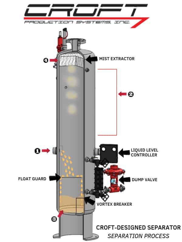
The Separation Process: All separators have at least three, and usually four sections comprising the separation process.
- The primary separation section
- The secondary separation section
- The liquid accumulation section
- The mist extractor section
1. Primary Separation Section
The primary separation section is the portion of the vessel around the inlet where the energy of the entering wellstream is dissipated. The purpose of this section and its mechanical components is to make the initial separation of liquid from the gas using many different methods deflectors or baffles.
Most of the liquid is moved to the liquid accumulation section. The larger quantities of liquid and large liquid drops immediately start falling as a result of the gravitational force.
In vertical separators the inlet deflector forces the liquid to change direction toward the vessel shell where it spreads out in a thin film, allowing solution gas to break out.
In horizontal separators, the liquid is usually directed against a deflector plate which may or may not be dish-shape. The liquid is thrown against the vessel shell to divert it from the main gas stream and allow rapid release of solution gas. In some cases, baffles are used in to break the liquid stream into smaller streams and droplets so that solution gas can be released faster.
2. Secondary Separation Section
The area of the separator immediately beyond the inlet deflector, between the liquid accumulation section and the mist extractor is called the secondary separation section. In this section the velocity of the gas and liquid is reduced because of the increased cross-sectional area. This allows the liquid particles to begin falling toward the liquid accumulation section as a result of gravitational force on the mass of the liquid particle.
In vertical separators, the gas velocity that extends up, tends to counter the gravitational force effect on the liquid particles as it exerts a resistant force on the particle. If the particle is large, the gravitational force will be the greater force, and the particle will settle to the bottom. Very small particles will be carried along with the gas as entrainment and will leave the separator, if not removed by some other device such as a mist extractor.
In horizontal separators the force is exerts at right angles to the gravitational force and does not hinder the particles’ fall to the liquid accumulation section. The resultant path of the particle is a diagonal path or trajectory toward the outlet of the separator. The horizontal separator must be large enough in cross-section and long enough so the reduction of the gas velocity and the diagonal paths for the bulk of the liquid particles will carry them into the liquid accumulation section.
The allowable velocity for the secondary separation section has been established by field tests of the various types of separators. Sizing is based on the allowable velocity for the gas stream in the secondary separation section. Most of the liquid particles that do not drop out of the gas stream will usually be removed from the gas stream by use of a mist extractor.
3. Liquid Accumulation Sections
All separators must provide an area where the collected liquid from the primary separation section, the secondary separation section, and the mist extractor can be held for a short period of time and then dumped to storage. The liquid accumulation section of a separator is usually comprised of three major categories liquid level controller, dump valves, control valves and sight glasses. Learn more about these parts and how they work on a separator.
The liquid retention time is normally one minute for two phase separation. This allows time for the solution gas to break out of the accumulated liquid.
In vertical separators a baffle plate is positioned between the liquid accumulation section and the secondary separation section. This is to insure little, if any, re-entrainment of liquid into the gas. It also minimizes wave action and turbulence on the liquid surface which could upset the liquid level control system.
Horizontal separators normally utilize approximately half of this section for liquid accumulation. Horizontal separators have less instantaneous surge capacity than vertical separators because of how they are shaped. The liquid retention time is normally three minutes for three phase separation. The large surface area at the gas liquid interface provides a release of solution gas.
Liquid outlet connections in either vertical or horizontal separators are usually located as far away from the inlet as possible to assure maximum liquid retention time for release of solution gas. These connections are also designed with anti-vortex baffles or siphon-type drains to prevent vortex development. The development of a vortex at the liquid outlet can cause gas to be re-entrained in the liquid being discharged.
4. Mist Extractors
The three types of mist extractors most commonly used in oil and gas separators are knitted wire mesh, vane, and centrifugal. Mist extractors cause small minute particles to form into larger droplets. As the gas stream passes through the mist extractor, the surfaces of the mist extractor itself are wetted with the entrained liquid particles. Continued contact with the wet surfaces causes them to combine into larger droplets. This action is promoted by the changing of direction forced on the gas by the extensive, long and windy path it must take to get through the mist extractor. When the droplets reach sufficient size to overcome the lifting force imposed by the velocity of the gas, they will fall into the liquid accumulator section of the separator. The standard mist extractor for CROFT separators is the knitted wire mesh.
- What are Knitted Wire Mesh Mist Extractors?
Knitted wire mesh mist extractors consist of horizontal or vertical pads of knitted stainless steel or monel wire mesh either in layers or wound for insertion into the separator.
On vertical separators the pad is placed in the horizontal position near the top of the vessel.
Horizontal separators use vertical pads near the gas outlet end of the separator. The pads are generally 4″ to 6″ thick and can vary in bulk density depending upon the particle size to be removed and the efficiency of removal desired.
Wire mesh mist extractors normally are designed to remove 99% of all liquid particles which are 10 microns or larger.
Read our blog on What is a Separator? to learn more about the specific applications for a separator.
Need to buy parts for a separator click here.
If you have any used separator for sale click here.
Need to buy used separator click here.
Need to buy a new manufactured separator click here.