An oil and gas separator is used for removing and collecting liquids from natural gas. A properly designed separator will also provide the release of entrained gases from the accumulated hydrocarbon liquids. These separators can go by many names or different purposes like liquid separators, oil separators, water and oil separators, etc., but the most common separators are a two-phase; separates gas from liquid or three phase; separates gas, oil and water. All of the separators use gravity to separate.
A well stream separator must perform the following:
- Primary Separation Section: the inlet deflector forces the liquid to change direction toward the vessel shell where it spreads out in a thin film, allowing solution gas to break out. This section is removing and separating the mostly-liquid hydrocarbons from the gas.
- Secondary Separation Section: the velocity of the gas and liquid is reduced because it enters a larger space. This allows the liquid particles to begin falling toward the liquid accumulation section as a result of gravity and removes most of the entrained liquid mist from gas.
- Liquid Accumulation Section: all separators must provide an area where the liquid can be collected. The liquid retention time is normally one minute for two-phase separation. This allows time for any gas to break out of the accumulated liquid and a measurable level. See parts of the liquid accumulation section.
- Mist Extractor Section: this section uses a mist extractor to remove any mist that is carried out with the gas. They are designed to force the gas through a torturous path to encourage the mist to accumulate onto the device and drip down to the liquid section.
If these functions are to be accomplished, the separator design must:
- Determine and dissipate the energy of the well stream as it enters the separator.
- Ensure that the gas and liquid flow rates are low enough so that gravity segregation and vapor-liquid equilibrium can occur.
- Minimize the movement in the gas section of the separator and reduce the velocity.
- Eliminate the draw in and transport of the separated liquid into the gas.
- Accumulate and control foams in the vessel.
- Provide outlets for gases and liquids, and maintain preset operating pressure and liquid levels.
- Provide relief, a pressure safety valve PSV, for excessive pressure in case the gas or liquid outlets should become plugged or the valves malfunction.
- Provide equipment (pressure gauges, thermometers, and liquid-level gauge) to help visually check the separator for proper operation.
- Provide the cleanout opening at points where solids will accumulate when solids are present in the inlet stream.
Basic Considerations
The goal for ideal separator selection and design is to separate the well stream into liquid-free gas and gas-free liquid. Ideally, the gas and liquids reach a state of equilibrium at the existing conditions of pressure and temperature within the vessel. As it is generally not economically justifiable to separate to the state of true equilibrium, industry consensus standards as to liquid retention time for solution gas break-out and liquid carry-over in the gas have been set. Retention rate recommendations can range of user but most stay within a range of 1-3 minutes, specifically in horizontal separators. In some cases, the process equipment and conditions downstream of a separator will dictate the necessary degree of separation and the actual design. To see how a separator works in oil and gas separation, read our other blog, How does a separator work in oil and gas?
Well stream Characteristics
The following characteristics influence vessel selection, in addition to the obvious quantities of liquids and gas to be separated:
- Proportions of gas and liquids composing the inlet stream
- Differences between the densities of the gas and liquids
- Differences between the viscosity of the gas and liquids
- Temperature and pressure at which separation is to be made
- Particle sizes of liquids in the gas phase or gas in the liquid phase
- Identification of impurities or special conditions such as H2S, C02, pipe scale, dust, foam, fogs, etc.
- Instantaneous flow rates otherwise known as slugs or heading
Separators are most manufactured in two basic shapes – vertical and horizontal. Each has specific advantages and the selection are usually based on which will accomplish the desired results at the lowest cost.
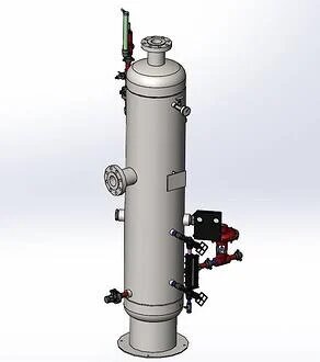
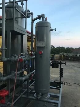
Vertical Separators:
Vertical separators are capable of handling large slugs of liquid and are therefore most often used on low to intermediate gas-oil ratio well streams. They are ideally suited as inlet separators to processing equipment since they can smooth out surging liquid flows. Special vertical separators called sand separators when excessive sand production is expected. Vertical separators occupy less floor space than comparably sized other types. This is an important consideration where floor space can be very expensive, as on an offshore platform. However, because the natural upward flow of gas opposes the falling liquid droplets, a vertical separator may be larger and more expensive than a horizontal separator for the same gas handling capacity.
Vertical Separator Applications
- Well streams having large liquid to gas ratios
- Well streams having sizable quantities of sand, mud, or other related substances
- Areas having horizontal space limitations, but little or no vertical height limitations
- Well streams or process flow streams which are characterized by large instantaneous volumes of liquid
- Upstream of other process equipment tolerating essentially no entrained liquid droplets in the gas
- Downstream of equipment causing liquid formation
Horizontal Separators
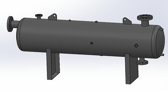
Horizontal separators are ideally suited to well streams having high gas-oil ratios, constant flow, and small liquid surge characteristics. Horizontal separators are smaller and less expensive than vertical separators for a given gas capacity. Liquid particles in the well stream travel horizontally and downward at the same time as a result of two forces acting upon them- the horizontal force of the gas stream and the downward force of gravity. Therefore, higher gas velocities can be permitted in horizontal separators and still obtain the same degree of separation as in vertical separators. The horizontal configuration is best suited for liquid-liquid-gas, or three phase, separations because of the large interfacial area available between the two liquid phases.
Horizontal Separator Applications
- Areas where there are vertical height limitations
- Foamy production where the larger liquid surface area available will allow greater gas break-out and foam breakdown
- Three phase separation applications for efficient liquid-liquid separation
- Upstream of process equipment which will not tolerate entrained liquid droplets in the gas
- Downstream of equipment causing liquid formation
- Well streams having a high gas to oil ratio and constant flow with little or no liquid surges
- Applications requiring bucket and weir construction for three phase operation
Buy new parts for a separator.
Learn more about our used separator options for sale.
Lean more about our new manufactured separator options.