CROFT has utilized several systems in the past including bubble towers, chemical injection systems, amine plants, etc. to treat H2S. But the cost is continuously an issue when treating trace amounts of H2S. We soon found out that the efficiency of the H2S Scavenger was the biggest monetary loss, followed by operational upsets like carry-over or condensate, which reduces the effectiveness of the chemical. We had a client that was opening up a second train with large volume swings that had trace amounts of H2S and we wanted to come up with a solution for them.
The Challenge:
In this second train, there were only trace amounts of H2S ranging from 5-45 ppm, but enough that required treatment to avoid affecting the large gas gathering facility. Now the volumes could swing from 8-30 MMcfd, changing every day, as more wells were coming online and making up for decline curves or operational upsets from existing wells. Gas temperatures averaged throughout the time at this location. Gas pressures did swing from 800-1100 PSI, but the outlet requirement needed to stay above 800 psi, which meant there could be only a minimum pressure differential across the system.
The Solution:
CROFT has designed our Chemical Injection Systems or CIS for other clients but it was for volumes below 5 MMcfd. So we needed to scale up this system to handle the volume swings of 8-30 MMcf and the pressure swings with having a minimum pressure differential across the system.
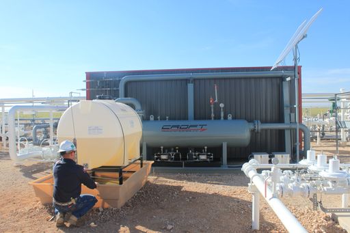
The solution we presented was the re-designed Chemical Injection System (CIS) 30 MM model.
This system was designed to have different static mixers to create enough turbulence and increase contact time without creating too much of a pressure differential. It has a modified two-phase separator to act as a bubble tower for efficient use of the chemical while providing proper separation. It was designed on the high size of 30 MMcfd range, but able to meet the lower swings with proper treatment. The major benefit was that an H2S analyzer on the downstream side of the unit was analyzing H2S and then correcting the pump speed of the scavenger injection accordingly to keep injection costs down.
The unit worked for the entirety of the project without interruption handling the volume swings, H2S swings, and maintaining outlet pressure. There is a quick chart below describing the volumes, pressures, and H2S inlet and outlet.
| Description | Inlet Parameters | Outlet Parameters |
| Gas Volume | 8-30 MMcfd | Same |
| Gas Temperature | 94 | Same |
| Gas Pressure | 800-1100 PSI | >800 PSI |
| H2S (PPM) | 5-45 PPM | <4 PPM |
Learn more about our Chemical Injection System.